AC solid state relays (SSRs) have been around for a long time. However, these early devices were not suitable for all situations, for example, because of severe distortion around the zero crossing of the waveform. MOSFET-based SSRs have been around since around 1984, when International Rectifier patented a MOSFET circuit capable of handling low-distortion AC. It is not known if this was the earliest example, but it was probably close.
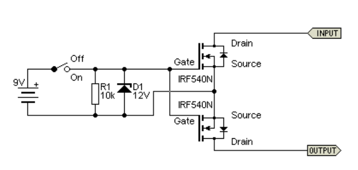
The diagram above shows the general idea of an AC SSR. Two N-channel switching MOSFETs are used, with their source and gate connected, and the signal and load connected to each drain terminal – it doesn’t matter which one, as the “switch” is symmetrical. But with two MOSFETs in series, the effective RDS(on) is twice that of a single device.
As there is no voltage between the gate and source, the MOSFET is off, so no current flows. Depending on the MOSFET used, they will fully conduct when the gate-to-source voltage exceeds around 7 volts. It is always a good idea to provide a 10-12V gate drive to ensure that they are always fully on. The Zener diode you see is to protect the insulation between the gate and the MOSFET channel. ,
The maximum rating of the gate insulation is usually around ±20V. Even a little distributed capacitance or resistance (such as moisture on the PCB) will cause the voltage to rise to destroy the device. Because the impedance is very high, the Zener is mandatory. If the Zener diode is not added, the capacitance of the drain will also cause problems.
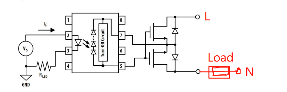
Although this concept is very simple, in fact, a lot of additional circuits are still required to achieve more reliable control. For example, the control circuit must be completely isolated from the switching MOSFET. At this time, you can consider using an optocoupler to achieve isolation, as shown in the following figure: