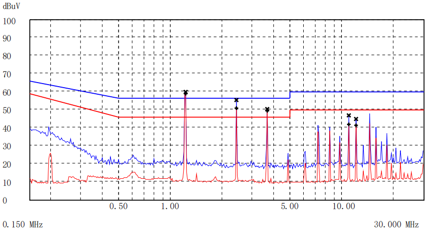
In the design of complex electronic devices, the frequency selection of crystals and switching power supplies is by no means trivial. When multiple devices of the same frequency coexist, the superposition of their fundamental frequency and harmonics will significantly amplify the EMI noise, putting the equipment at risk of exceeding the standard. In this article, we will explore how to optimize the electromagnetic compatibility from the source through the spectrum allocation strategy.

The core of the problem: same-frequency superposition effect
The pitfalls of normalized purchasing: in order to simplify the procurement process, the choice of the same specification crystal or DCDC switching frequency results in the superposition of the same-frequency fundamental and harmonic energies and the enhancement of radiation noise.
The value of spectrum allocation: Consciously stagger the operating frequency to disperse the noise energy. Even though the number of frequency points increases, the intensity of a single point is significantly reduced, making it easier to meet EMC requirements.
Crystal Frequency Selection Strategy: The Art of Parity Harmonics
Case Scenario: An 8MHz crystal is already used on the motherboard, and another board needs a new crystal, either 8MHz, 16MHz, or 24MHz.
Eliminate the same frequency (8 MHz): fundamental and harmonics are directly superimposed, with the highest risk of noise enhancement.
Harmonic characterization key point: 50% duty cycle square wave, even harmonic theory is zero (based on the Fourier transform).
Spectrum analysis:
16MHz & 8MHz: 16M (fundamental) → 48M (3rd), 80M (5th)…; 8M → 24M (3rd), 40M (5th)… — the key odd harmonics are perfectly staggered.
24MHz & 8MHz: 24M (fundamental) → 72M (3rd), 120M (5th)…; 8M → 24M (3rd), 48M (6th), 72M (9th)… — At 24MHz, 72MHz, etc. Overlap.
Conclusion: A combination of 16MHz and 8MHz is preferred. Design Guideline: Avoid odd multiples of crystal frequency (e.g., 3x, 5x).
Special Challenges of DCDC Power Supplies
PWM duty cycle dynamics: almost impossible to stabilize at 50%, resulting in both odd and even harmonics.
Frequency selection principle: Strictly avoid the integer multiple relationship of fk1 = n * fk2 (or fk2 = n * fk1) (regardless of n odd-even), preventing superposition of fundamental and all harmonic components.
Typical case: 125 MHz crystal with 500 MHz radiation
Problem: The 500 MHz frequency point in the RE test is exceeded by exactly 4 times the frequency of the 125 MHz crystal.
Misconception Analysis: Trying to suppress 500 MHz radiation by filtering 125 MHz.
Core mechanism: After the 125 MHz signal is input to the PHY chip, the internal circuitry performs 2^n times frequency doubling (4 times frequency doubling in this case) to generate a new 500 MHz strong signal.
Solution:
Source treatment: Enhance filtering, shielding, or layout optimization at the 500 MHz output of the PHY chip.
Spectrum planning: If possible, avoid using base frequencies (e.g., 125 MHz) that are susceptible to high-frequency multiplication.
Spectrum Allocation: Key to System-level EMI Design
Core Idea: At the architecture design stage, globally plan key frequency sources (crystal, DCDC switching frequency, clock generator) to disperse their fundamental and major harmonics actively.
Value: Significantly reduce the intensity of single-point noise and reduce the difficulty and cost of remedial measures such as filtering and shielding at a later stage.
Design Revelation: Excellent EMC design begins with system planning. Resolving the noise superposition crisis at the signal source through subtle spectrum allocation is the cornerstone of building highly reliable electronic equipment. The next time you lay out a crystal or set a power supply frequency, take the spectrum map into account—it may be the most cost-effective EMC solution.


