1. Introduction
In applications such as home appliance control panels, simple indicator/relay drives, electricity meters, and traditional timers/temperature controllers, it’s often necessary to derive a low-voltage DC power supply of tens of milliamperes from an AC220V (or AC110V) supply. If the output current is very low (typically 5–80mA), cost and size are extremely sensitive, and the circuit is completely enclosed and inaccessible, a “capacitor step-down” solution (more accurately, “capacitor current limiting”) is considered. This solution uses series safety capacitors to create capacitive reactance to limit current, rather than true “step-down conversion.” Therefore, its safety properties differ significantly from those of an isolation transformer or switching power supply: the output is directly electrically connected to the mains, lacking safety isolation.
2. Operating Principle Overview
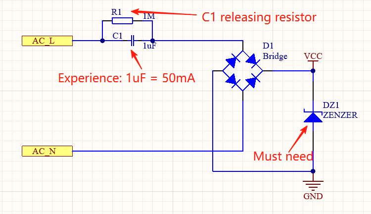
Connect an AC safety X2 capacitor Cx in series. The capacitor’s capacitive reactance, XC = 12πfCXC = 2πfC1, limits the AC current flowing through the downstream stage. Ideally, the capacitor consumes no active power (generating only reactive power), so its heat generation is much lower than that of resistor-based current limiting. After rectification and filtering, the resulting pulsating DC is stabilized to a nearly constant low-voltage output using a Zener diode or LDO.
3. Comparison with Transformer / Isolated Supplies
| Dimension | Capacitive Dropper | Small 50/60 Hz Transformer | Isolated Flyback / Charger Type |
|---|---|---|---|
| Safety isolation | None | Yes | Yes |
| User‑touchable output | Prohibited (unless additional isolation) | Allowed | Allowed |
| Cost (at very low current) | Very low | Medium | Medium / slightly higher |
| Size (≤0.5 W) | Very small | Large | Small (but more complex) |
| Temperature rise / efficiency | Often low active efficiency (depends on regulation method) | Moderate | Moderate to high |
| Current scalability | Poor (C grows quickly → surge & size issues) | Limited | Good (easy to scale) |
| EMI / surge robustness | Weak | Strong | Design‑dependent |
4. Estimating Available Current
The ideal AC current (RMS) is determined by the series capacitor: IAC = Vrms XC = 2πfCVrms IAC = XC Vrms = 2πfCVrms
To convert this to the average sustainable DC output current after rectification, the rectification method and waveform duty cycle must be considered. Common engineering empirical coefficients are as follows (estimated when using appropriate filter capacitors and a near-constant load):
Average available DC current for half-wave rectification: IDC,half ≈ 0.44 × Vrms XC = 0.44 × 2πfCVrms
Average available DC current for full-wave rectification: IDC,full ≈ 0.89 × Vrms XC = 0.89 × 2πfCVrms
For example, at 50 Hz, 220 Vac, and C = 1 µF: IDC,half ≈ 0.44 × 2π × 50 × 1 µF × 220 ≈ 30 mA
IDC,half ≈ 0.44 × 2π × 50 × 1 µF × 220 ≈ 30 mA IDC, full ≈ 0.89 × 2π × 50 × 1μF × 220 ≈ 60mA IDC, full ≈ 0.89 × 2π × 50 × 1μF × 220 ≈ 60mA
Note: The above formula is an approximate empirical value. The actual load is affected by
5. Half‑Wave vs Full‑Wave Rectification
- Advantages of full-wave rectification: Doubles the pulsation frequency, lowers output ripple, allows for appropriate reductions in capacitance, and results in approximately twice the average available current of half-wave rectification. Peak pulses are more uniform, helping to reduce Zener power dissipation fluctuations.
- Advantages of half-wave rectification: Fewer components (saving two diodes or bridge rectifiers) and a lower bill of materials (BOM).
- Safety: Both have the same inherent safety risk (both are non-isolated and floating), and there’s no physical basis for claiming full-wave rectification is less safe.
- Choice Recommendation: If board space permits and a more stable output is required, full-wave rectification is preferred.
6. Regulation Methods
- Zener diode + filter capacitor
- Lowest cost
- Load variation → large output voltage deviation
- When no-load, most of the current-limiting current is dissipated by the Zener, requiring verification of the Zener power dissipation. PZ = (IAC, equivalent − Iload) × VZ
- Zener + series resistor + simple LDO
- Reduces Zener continuous dissipation and improves load voltage stability
- Adding components still results in low efficiency
- Switching power stage (rarely used in such cost-critical applications)
- Complexity and cost negate the original purpose of “capacitor step-down”
This type of circuit is typically used to achieve low-cost, non-isolated, low-current power supplies. Its output voltage typically ranges from a few volts to tens of volts, depending on the Zener diode used. The current it can provide is proportional to the current-limiting capacitor capacity. When using half-wave rectification, the average current per microfarad of capacitor is: (SI units).
7. Key Components and Design Notes
| Component | Design Notes |
|---|---|
| Series limiting capacitor (Cx) | Must be safety‑rated X2 (≥275 Vac). Include tolerance and aging (capacitance decreases over time) in margin. |
| Series resistor (inrush / fusible) | 22–100 Ω typical; limits plug‑in surge and may act as a weak fuse. Do not rely on it as the sole protective fuse in high‑risk products. |
| Bleeder resistor | 0.47–2.2 MΩ across Cx to discharge voltage to a safe level within a few seconds after power off. |
| Rectifier | Small bridge (e.g. MB2S / MB6S) or four discrete diodes (1N4148 / 1N4007). Full‑wave preferred for better ripple behavior. |
| Filter electrolytic | 10–470 µF, voltage rating ≥ 1.5–2 × Vout. Larger value lowers ripple but increases inrush stress. |
| Zener diode | Power rating margin ≥ 2× peak/continuous dissipation; choose low leakage types. |
| Surge protection | MOV on input if environment has frequent surges (adds cost). |
| PCB layout | Maintain adequate creepage/clearance between mains and low‑voltage nodes (even though not isolated) to prevent contamination or condensation shorts. |